C. Details of the Model |
C. Details of the Model |
b. Radiation Scheme
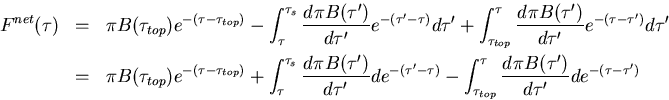
Here, the radiation scheme used in the numerical calculations and the characteristics of the scheme will be described. The key is to discretize the radiative flux equation in two ways and then join the two discretized equations, which allows radiation calculations for a gray atmosphere with an arbitrary optical depth profile.
Finite-Difference Representation of Radiative Flux
Net upward radiative flux for the case of a gray atmosphere is given by the following equation:
where
is optical depth at the top of the atmosphere, thus is
. πB is equal to σT4.
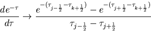
Here, the radiative flux equation is discretized in the same way as in Nakajima et al. (1992), and thus
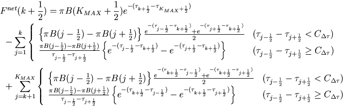
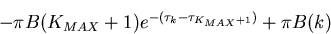
Here, KMAX represents the upper-most layer, and KMAX = 32 in a typical model calculation. The radiative flux is calculated by joining two sets of discretized equations. Specifically, the integrals for the contributions to net upward radiative flux from optically thin layers and optically thick layers are evaluated using the upper and lower options in the equation, respectively. The fraction of the usage of the upper and lower options in the equation changes according to the value of
. If a significantly large value is taken for
There exists no
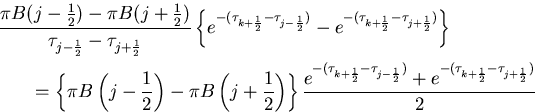
that makes the upper and lower options identical. If such
needs to hold. Rearranging this condition by letting
leads to
Unfortunately, no solutions exist for this equation. More accurately, a discontinuity emerges in the evaluated fluxes at the altitude at which the transition between the two options occurs. However, the actual difference between the evaluated fluxes is almost negligibly small. In fact, no evident visible discontinuities exist in the vertical profiles of the radiative flux. (For more information, see Figure 5 of Characteristics of One-Dimensional Radiative-Convective Equilibrium Solutions.)
The above-mentioned complex procedure is necessary because problems arise if either the upper or lower option in the discretized radiative flux equation alone is used. The reasons that the problem arises will be described below, and the values of
For the Case of Large CΔτ
First, the extreme limits are considered in which
for the evaluation of net upward radiative flux. Properly, Fnet should be represented as
(a) 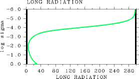
(b)
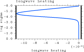
Figure 1: The results for the case of
In this example calculation, the values of σT4 and net upward radiative flux are

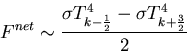
For the case of L32, the above-described phenomenon is more amplified. Net upward radiative flux starts increasing near log10σ = - 3 from higher to lower altitudes, however, it starts decreasing again around log10σ = -1 (Figure 2(a)). This profile results because the net upward radiative flux is determined by σT4k-1 - σT4k below log10σ = -3.0. The decrease in net upward radiative flux from higher to lower altitudes near the surface is attributable to small vertical grid intervals near the surface. The net upward radiative flux values around log10σ = - 1 for the case of
(a) 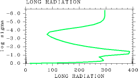
(b)
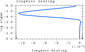
Figure 2: The results for the case ofIn the case of L32, a discontinuity arises in the middle layer of the vertical profile of radiative flux for
For the Case of Small CΔτ
The behaviors of the results from the extreme limit of a significantly small
becomes zero in the optically thin layer, that is, in the upper, low-temperature layer. When this option is used, the values of τj-1/2 and τj+1/2 become significantly small. For this reason, the calculation yields a numerically equal value for
and
within the range of numerical error, resulting in zero for the difference between the two terms. Properly, the values of both
and
become quite small, leading to
In the layer above the altitude at which

becomes zero, the downward radiative flux is determined by
is thus smaller than the correct value of downward radiative flux. Similarly, for the upward radiative flux, some of the additive terms drop away above the altitude at which
(a) 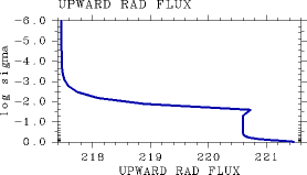
(b)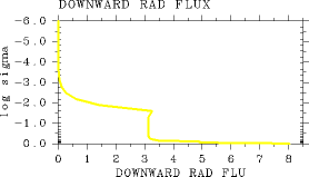
Figure 3: Radiative flux profiles obtained withFurthermore, the above-mentioned problem occurs in a more extreme manner with increasing vertical grid resolution. In the case of L1000, the value of OLR can no longer be calculated correctly, and thus an accurate relationship between Tg and OLR cannot be obtained (not shown).
Consequently, the upper option of the discretized equation cannot be applied for the entire atmospheric layer. However, it has been confirmed that radiative flux can be calculated without difficulties for
Summary
If the upper option of the discretized radiative flux equation alone is used, a problem arises in the radiation calculations for an optically thin atmosphere. Furthermore, the lower option of the discretized radiative flux equation alone cannot be used for an optically thick atmosphere. However, a combination of the two options of the discretized equation allows radiation calculations of a gray atmosphere with an arbitrary profile of optical depth. In this regard, the value of CΔτ that prescribes the switchover between the discretized equations needs to take a value between 1.0 and 10-7. Based on the results above, a value of 0.1 is adopted for CΔτ in the present study.
| C.b. Radiation Scheme |